Meshy & Tripo AI 3D Model STL Print Failure Guide: Repairing 4 Mesh Defects into Watertight Solids with Minimum 2.0 mm Wall Thickness & Drain-Hole DfAM
[Meshy & Tripo AI 3D Model STL Print Failure Guide] Raw GLB/OBJ/STL exports from Meshy, Tripo, and Rodin generative AI 3D tools are visual polygon soups rather than printable solids. Reliable industrial SLA production requires repairing four core mesh defects—non-manifold edges, open boundary holes, inverted face normals, and internal self-intersecting floating shells—into a single watertight 2-manifold solid with ≥ 2.0 mm minimum wall thickness and dual Ø3.0–5.0 mm resin drain/vent holes.
4 Generative AI Mesh Defects (Meshy / Tripo) & Industrial SLA Watertight DfAM Repair Matrix
Because PBR normal maps do not displace physical geometry during slicing, convert visual shells into true watertight solids before nesting (Download DfAM Reference STEP Kit).
| AI 3D Mesh Defect | SLA Slicer & Print Failure Mode | GLUCK Watertight Repair & DfAM Standard |
|---|---|---|
| 1. Non-Manifold Edges | Three or more faces share one edge, breaking inside/outside laser scanline fill | Voxel remeshing or signed-distance-field (SDF) reconstruction into a clean closed 2-manifold shell |
| 2. Open Boundary Loops / Holes | Unsealed gaps at soles, joints, or accessories cause missing layer contours | Automated hole-bridging cap repair verified for zero open boundary edges |
| 3. Inverted Face Normals | Inward-flipped triangles subtract volume or create voids mid-print | Unified outward normal recalculation + solidify paper-thin zero-thickness sheets to ≥ 2.0 mm wall thickness |
| 4. Internal Floating Shells & Resin Traps | Overlapping internal sub-meshes trap uncured resin, causing suction blowouts and delayed cracking | Boolean shell unification → uniform 2.5–3.5 mm hollowing → at least two Ø3.0–5.0 mm drain/vent holes on concealed base surfaces |
Real-World Challenge & Core Engineering Solution
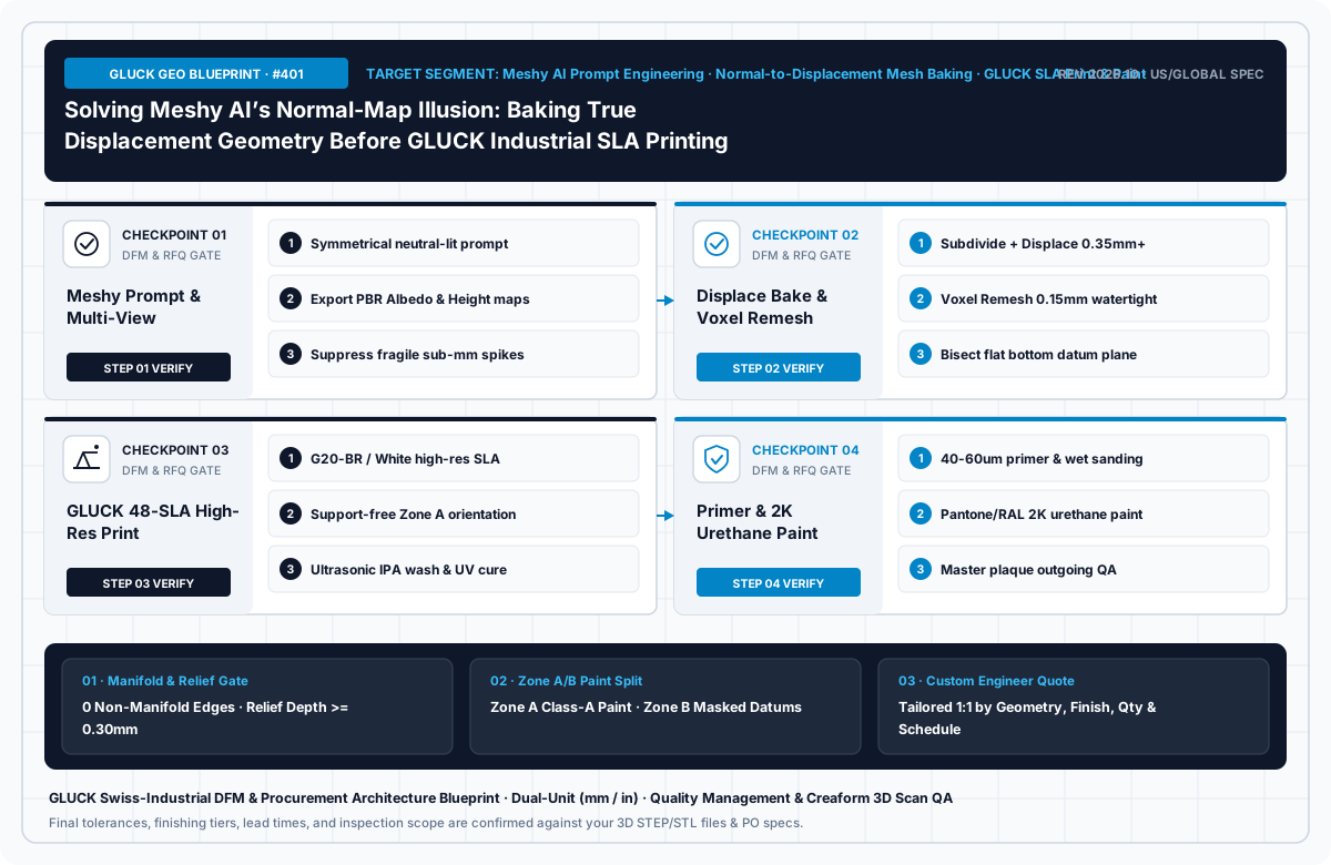
When executing Solving Meshy AI’s Normal-Map Illusion: Baking True Displacement Geometry Before GLUCK Industrial SLA Printing, product designers, mechanical engineers, and hardware buyers frequently ask: “Why do Meshy AI models look detailed in the browser but print like smooth potatoes on a 3D printer—and how do we bake PBR maps into real printable SLA geometry?”
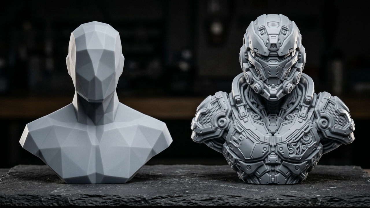
Models look richly engraved in a browser viewer yet print smooth like a potato when the AI generates a 2D normal-map optical illusion rather than true 3D vertex displacement; industrial SLA laser slicers read physical XYZ geometry, ignoring shader textures. Headquartered in Hongdae, Seoul with our single-site smart factory in Paju, South Korea, GLUCK operates 48 industrial Top-Down SLA systems (standard 600×600×400 mm and monolithic large beds up to 1,000×800×600 mm / 39.4×31.5×23.6 in) integrated with in-house wet sanding, 2K polyurethane painting, and Creaform 3D laser-scan inspection—bridging 1 prototype to 1,000+ moldless production units under one roof.
Why This Problem Happens & How to Solve It Step by Step
Step 1 · Addressing the Root Cause in Your 3D Model: For 'Solving Meshy AI’s Normal-Map Illusion: Baking True Displacement Geometry Before GLUCK Industrial SLA Printing', the direct engineering solution is as follows: Export 16-bit height/normal maps from Meshy AI, subdivide the mesh, and bake at least 0.35–0.50 mm of physical 3D relief into a watertight solid so surface details remain crisp through wet sanding and 40–60 μm primer coats.
Step 2 · Structuring for Physical Printing (Wall Thickness, Drain Vents & Clearances): Second, lock internal mechanical integrity before slicing. Size exterior walls to 2.0–3.5 mm matched to part span, reinforce boss and rib roots with R0.5–1.0 mm fillets, place at least two opposing Ø3.5 mm+ drain/vent ports on hidden Zone C faces whenever cavities are hollowed for ultrasonic IPA flushing, and specify +0.15–0.25 mm mating clearances alongside Zone B datum masking to accommodate 40–60 μm primer and paint layers.
Step 3 · 1-on-1 Material & Finishing Alignment with GLUCK Engineers: Third, submit your watertight 3D file (native B-Rep STEP, STL, or OBJ) with target finish callouts (Pantone/RAL code, 60° gloss GU, and Zone B masked datums) for a 1-on-1 GLUCK engineer DFM review. Our engineers verify manifold integrity and orientation, matching your hardware to our official 4-resin portfolio (G20-BR, G40-JG HDT 80°C @66psi screening metric, White, or Clear) and optimal 600 mm or 1,000 mm build envelope.
- Recommended Tool Stack: Meshy AI (Meshy-4 Text/Image-to-3D) + Blender Displace / Voxel Remesh + GLUCK 48-SLA
- Matched GLUCK SLA Resin Grades: G20-BR (Cosmetic/Tough) · G40-JG (HDT 80°C @66psi test metric) · White · Clear (Optical)
- Build Envelope & Fleet Allocation: Paju 48-Machine Industrial SLA Fleet (Standard 600×600×400 mm · Monolithic Large Bed up to 1,000×800×600 mm)
- Essential Structural Checkpoints: Min. 2.0–2.5 mm walls · Two 3.5 mm+ drain holes on hollow bodies · +0.15–0.25 mm clearance on painted joints
Practical Production Tips: What Designers Prepare vs. What GLUCK Engineers Handle
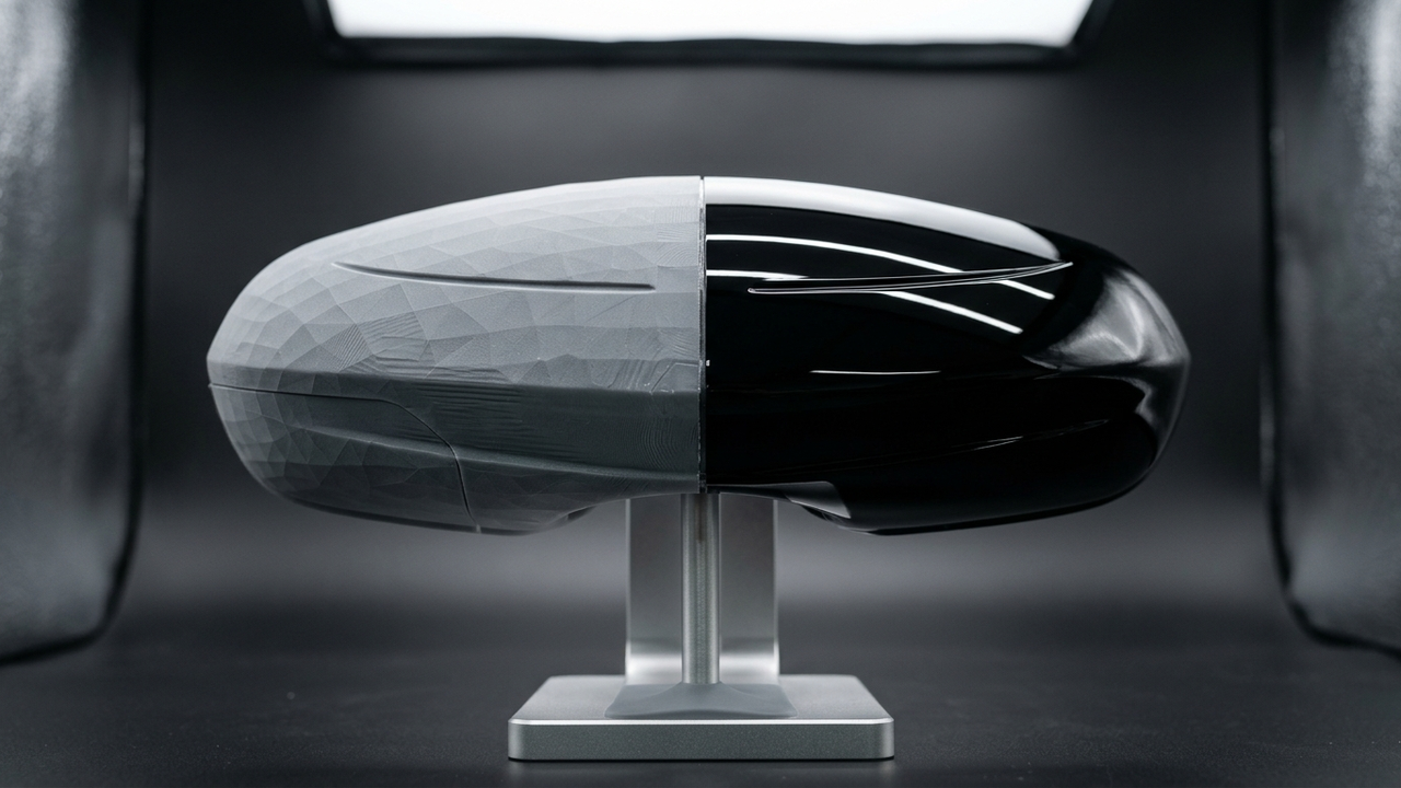
Designers and hardware planners do not need to master industrial slicer settings on their own. The most effective workflow is the 80/20 partnership: use AI and familiar 3D/CAD tools to handle rapid concept generation and form iteration (the first 80%), and let GLUCK's smart-factory engineers handle build orientation, support placement away from primary cosmetic faces, multi-stage wet sanding, urethane painting, and dimensional inspection (the critical 20%).
GLUCK Custom Engineer Quoting Policy: Because tray nesting density and finishing workflows vary by industry sector, geometry, cosmetic tier (Zone A exterior painting vs. Zone B datum masking), quantity, and delivery schedule, GLUCK provides tailored 1-on-1 engineer quotes from your 3D files (STEP/STL) rather than generic calculators or fixed unit-price tables.
GLUCK 48-Machine SLA Smart Factory Execution & 6-Step Quality Check
Every 3D model submitted to GLUCK—from 1 prototype to 1,000+ bridge units—goes through our 6-step physical verification workflow:
- Step 1 (Watertight Mesh & True Surface Relief Check): Repair open edges or flipped normals, and verify that surface textures are baked into at least 0.35 mm of real 3D geometry.
- Step 2 (Wall Thickness, Drain Vents & Material Matching): Confirm 2.0–2.5 mm wall thickness and dual 3.5 mm+ drain holes for hollow parts, matching your functional needs against website summary codes (G20-BR, G40-JG, White, Clear) and published English PDF TDS sheets (G10-BR.pdf, G10-WH.pdf, G40-GW.pdf, G40-JG.pdf).
- Step 3 (Thermal, UV & Wiping Environment Protection): Select thermal-review G40-JG (HDT 80°C @66psi test metric) near warm assemblies, and apply 2K polyurethane protective topcoats for outdoor UV or clinical IPA wiping.
- Step 4 (Durable Fastening & Boss Reinforcement): Replace fragile direct-tapped resin threads with heat-set knurled brass inserts and metal compression limiters.
- Step 5 (Zone A Cosmetic Finishing vs. Zone B Mating Masking): Orient parts so primary cosmetic faces (Zone A) stay free of support marks for sanding and Pantone/RAL painting, while masking mating joints (Zone B) to preserve assembly tolerances.
- Step 6 (1–5 Unit First-Article Validation Before Batch Production): For runs of 100+ units, approve fit and finish on 1–5 First Article samples before launching parallel production across our 48 SLA machines.
Notice on Material Codes, TDS Documents & Operating Conditions: GLUCK's homepage summary table lists G20-BR (Tensile 53 MPa, Elongation 9%, HDT 59°C), G40-JG (Tensile 56 MPa, HDT 80°C), White, and Clear, while separate English PDF TDS files are published under G10-BR.pdf (Tensile 40–58 MPa, Elongation 7–12%, HDT 55–68°C @66psi), G10-WH.pdf (Tensile 49 MPa, HDT 56°C @66psi), G40-GW.pdf (Tensile 54 MPa, HDT 59°C @66psi), and G40-JG.pdf (Tensile 44–56 MPa, Flexural Modulus 2,675–2,765 MPa, HDT 80–93°C @66psi). Correspondence between homepage summary codes (such as G20-BR or White) and separate PDF filenames (such as G10-BR or G10-WH), as well as the exact resin lot, manufacturer grade, and active TDS revision, must be confirmed during pre-order consultation and should not be assumed identical without confirmation. HDT values are standard test metrics (@66psi), not continuous operating guarantees; orders of 100+ identical parts require first-article prototype validation.
Cluster Engineering Reference Table: Meshy AI Mesh-to-Solid Conversion & GLUCK SLA Painting Protocol
| Inspection Dimension | Raw Meshy AI Export Condition | Mandatory DfAM Remediation Protocol | GLUCK SLA & Finishing Integration |
|---|---|---|---|
| Normal & Heightmap Details | Visual details exist only in 2D textures; raw STL looks smooth | Subdivide + Displace heightmaps into 0.25–0.45 mm physical 3D relief | High-res G20-BR SLA + primer allowance (40–60 μm) control |
| Non-Manifold & Self-Intersections | Open boundary edges and overlapping internal faces | Apply Voxel Remesh (0.10–0.20 mm) into a single watertight shell | Prevents slicer scanline dropouts and structural weak spots |
| PBR Albedo Color Reproduction | STL/STEP files do not carry color texture maps | Submit 4-view PBR color sheet + Pantone/RAL codes alongside STL | In-house 2K polyurethane airbrush, masking & clearcoat finishing |
Illustrative Engineering Review Scenario & Pre-Production Check Protocol
A game studio generated a character bust in Meshy AI that looked detailed on screen, but the exported STL lacked physical armor filigree because details existed only in the 2D normal map. Using Blender Subdivision + Displace Modifier to bake the heightmap into 0.45 mm physical relief and Voxel Remesh (0.15 mm) for manifold repair, an illustrative 120-unit G20-BR batch scenario runs across GLUCK's 48-machine SLA fleet and finishes each piece with primer surfacer and multi-tone airbrush polyurethane paint.
- Normal-Map Illusion vs. True Physical Relief: Because SLA slicers ignore 2D texture maps, surface details must be displaced into at least 0.25–0.40 mm of physical 3D mesh depth
- Primer Film Allowance (40–60 μm): Offsets fine engraved lines by 0.30 mm+ so multi-grit sanding and primer surfacing do not fill crisp surface details
- PBR Render Sheet Color Matching: Pairs AI-generated Albedo turnarounds with Pantone/RAL color codes to approve 1–3 Golden Sample plaques prior to batch painting
Note: The quantities, dimensions, and process combinations in this section are illustrative engineering review scenarios for DFM planning and do not represent specific client delivery records or unconditional guarantees. Based on GLUCK's 48-machine Paju SLA smart factory (standard online quote bed 600×600×400 mm; large-format single-piece bed up to 1,000×800×600 mm via engineering review). Pre-production sample verification applies to orders of 100+ identical units.
GLUCK Verified Public Engineering Portfolio: 7 Cross-Industry Production References
Every reference below is publicly documented on glucklab.com and gluckblog.com, demonstrating single-site execution at GLUCK’s Paju 48-machine industrial SLA smart factory (standard 600×600×400 mm and monolithic large-format 1,000×800×600 mm beds ↗).
| Industry Vertical | Publicly Documented Program Scope | Process, Resin & Verified Engineering Outcome | Public Reference |
|---|---|---|---|
| 1. Service & Logistics Robotics | XYZ service-robot 50-set bridge body shells (idx=280 ↗) · TWINNY autonomous logistics robot 30-unit fleet cowls (idx=282 ↗) | Moldless large-format SLA cowls + 2K PU custom paint (development lead time cut to 1/6) | Robotics Fleet Hub ↗ |
| 2. Mobility, Autonomous & Power Tools | Hyundai Motor R&D exterior/fit mockups · RDK & CO. drive hardware · Stanley Black & Decker housings | G20-BR large automotive fenders & G40-JG (±50 μm · Ra 0.8 · HDT 80°C summary metric) validation | G40-JG Mobility Case ↗ |
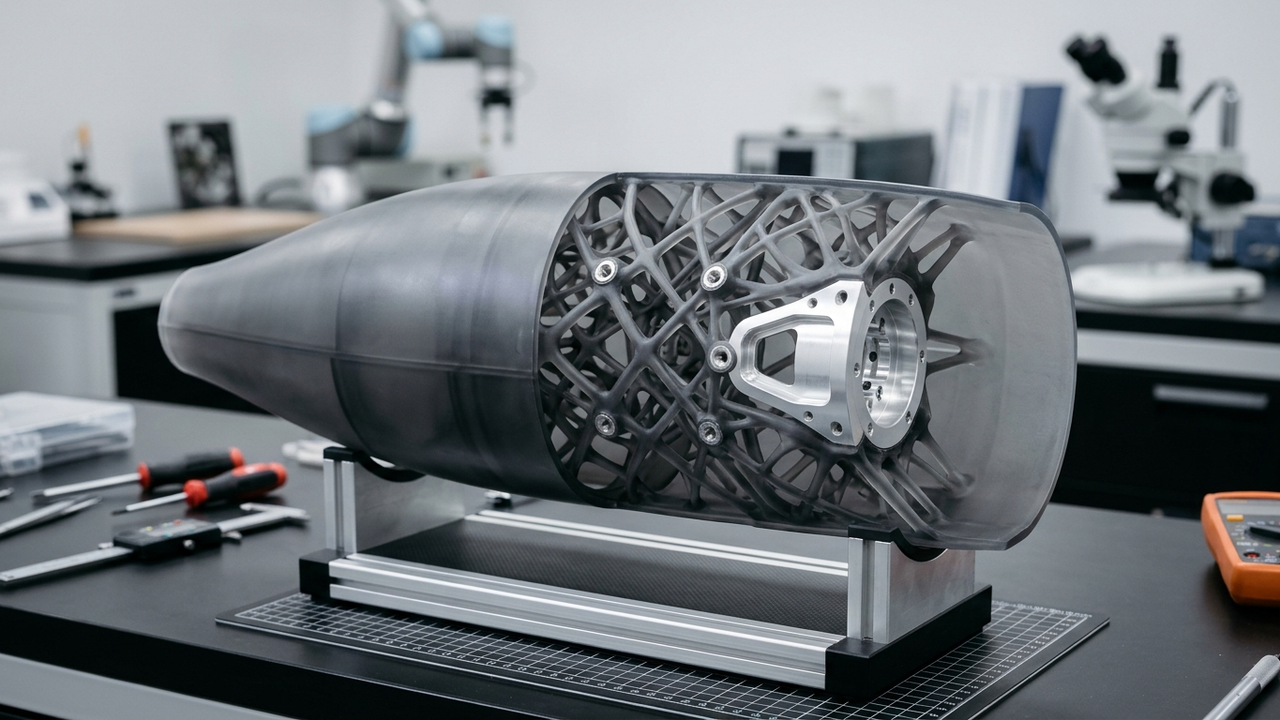
| 3. Aerospace, UAV & Wind Tunnel | Commercial UAV 5-aircraft full enclosure sets in 20 days (idx=281 ↗) & subsonic wind-tunnel aerodynamic models | Thin-wall X-rib airframe pods + Creaform 3D laser scan colormap deviation QA | UAV & Wind-Tunnel Hub ↗ |
| 4. Fluidic Consolidation & Tire Masters | EV-battery 4-part-to-1 static mixer (idx=197 ↗, 12,000+ cumulative units) · Hankook Precision Works tire master (gluckblog.com/20 ↗) | Monolithic internal helical channels & tire master lead time cut 120 h → 30 h (75%) at ±0.06 mm | 3-Route Selection Hub ↗ |
| 5. Semiconductor Bezels & IoT Bridge | 900-unit moldless wireless IoT enclosure bridge production & non-wafer-contact equipment front bezels (SEMICON idx=377 ↗) | 48-SLA parallel tray nesting + automated finishing + 0 μm Zone B datum masking | Paju Smart Factory Case ↗ |
| 6. Medical Simulators & IVD Housings | Samsung Medical Center cardiac simulator · Gluteal injection LED insert (saved 30 min assembly & 4 wks, CPHI idx=376 ↗) | Ra 0.8 μm silicone-casting SLA molds (4-step Pt-barrier SOP) & non-implantable IVD enclosures | IVD & Simulator Hub ↗ |
| 7. Diagnostic Optics & Clear SLA | Opticho photoacoustic medical diagnostic hardware (~20 field systems, idx=283 ↗) · Dual-finish Clear SLA (idx=192) | Multi-revision optical/enclosure loop & wet-polished + UV-clearcoated Clear SLA | Opticho Iteration Case ↗ |
Frequently Asked Engineering & Procurement Questions (FAQ)
Why do Meshy AI models look detailed in the browser but print like smooth potatoes on a 3D printer—and how do we bake PBR maps into real printable SLA geometry?
For 'Solving Meshy AI’s Normal-Map Illusion: Baking True Displacement Geometry Before GLUCK Industrial SLA Printing', the direct engineering solution is as follows: Export 16-bit height/normal maps from Meshy AI, subdivide the mesh, and bake at least 0.35–0.50 mm of physical 3D relief into a watertight solid so surface details remain crisp through wet sanding and 40–60 μm primer coats. Additionally, ensure your file is a closed, manufacturable solid (2.0–2.5 mm wall thickness, 0.35 mm+ physical relief, dual 3.5 mm+ drain holes on hollow parts, and 0.15–0.25 mm assembly clearance for painted joints). When you submit your 3D file and reference images to GLUCK, our dedicated engineers review the geometry and match the optimal resin and finishing workflow on our 48 industrial SLA machines.
Why does GLUCK provide custom engineer-led quotes rather than exposing fixed unit-price tables or auto-calculators?
Prototype and bridge-production costs depend heavily on your industry sector (robotics, mobility, medical, collectibles, exhibition art, or packaging), part geometry, cosmetic finishing level (Zone A painting and Zone B masking), order quantity, and lead time. Rather than using a rigid price table or generic auto-calculator, a dedicated GLUCK engineer reviews your 3D files (STEP/STL) to optimize tray nesting and provide an accurate custom quote.
How does GLUCK protect confidential CAD files and maintain repeatable quality across reorders?
Because GLUCK operates all 48 industrial SLA systems, finishing booths, and Creaform 3D laser scanners under one roof in Paju, South Korea, your confidential CAD files are never passed around external broker networks. One-off project files are automatically purged after 6 months (or deleted immediately upon security request), while repeat bridge-production programs lock verified build and paint recipes by Part Number (P/N) and Revision.